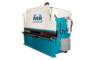
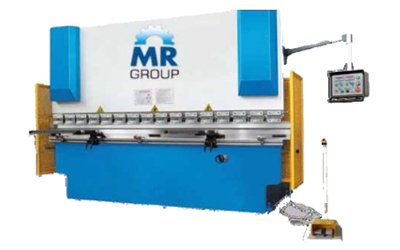
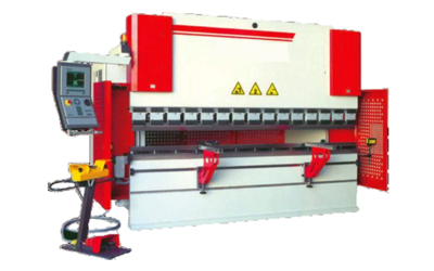
We are Manufacturer, Supplier and Exporter of Hydraulic Press Brake Machines, NC Hydraulic Press Brake Machines, CNC Synchro Hydraulic Press Brake Machines, Hydraulic Press Brakes, NC hydraulic Press brakes, CNC Synchro press brakes and our setup situated in Pune, Maharashtra, Ahmedabad, Gujrat, India.
MR Enterprises Hydraulic Press Brakes are highly productive, accurate, and economical. Through advanced design and construction, DEV Hydraulic & Machinery offers quality Hydraulic Press Brakes that provide simplified and easily accessible controls for optimum operator efficiency and output.
Pair of hydraulic cylinders is synchronized mechanically by a heavy-duty torque tube construction. This facility ensures absolute parallelism between ram and table working surface. These press brakes are manufactured to high standards of lifetime durability and precision accuracy.
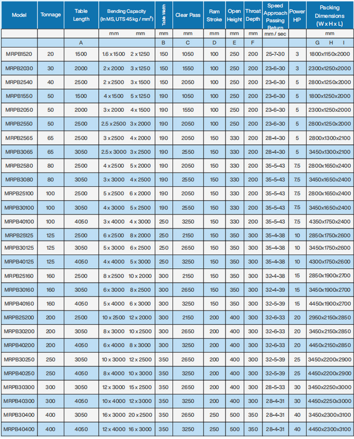
- Tonnage - 20 MT to 600 MT
- Length - 1500 mm to 6000 mm
- Bending Length (mm) 1500mm / 2000mm / 2500mm / 3000mm / 4000mm
- Accuracy ± 0.03mm
- Thickness - Up to 25mm
- Back Gauge Length - As per requirements
- Accurate right angle welded steel frame with tested material gives accu-rate bending
- Accurately Synchronized cylinders for equally vertical force of RAM at full length.
- Use of hardened Pin and Bushes gives less maintenance.
- Flexible sheet support for longer and heavier plates/sheets.
- Emergency stop push switch with moveable console including motor on/off, RAM up/ down & cycle selection switch.
- Three Operating Mode - Auto, Inch & Single cycle
- Centrally lubrication system by Hand pump at all pin, bushes and joints.
- Five way V- Block (EN-31) in one and suitable Blade
- Fine stroke adjustment Rod with limit switches.
- V-Block Die & Punch
- Operating Mode
- Backgauge With Micro Setting
- Front Sheet Support
- Centralized Lubrication System By Manual Pump
- Electrical control pane! with selection of 'AUTO', INCH' & 'SINGLE CYCLE AUTO1 mode operations
- Movable workstation with pair of foot switch
- Pair of lifting Sinks
- Pair of sheet support
- Fine stroke adjustment rod with limit switch
- Front operated Manual back gauge with micro setting
- One suitable five way die & Punch of EN-8** (unhardened and ungrounded)
- Centralized lubrication system with flow control valves for adequate lubrication
- Ram tilting arrangement on selected models
- Manual, Auto P. Program mode selection through screen
- Two axis dedicated CYB TOUCH 6 controller with s.r colour touch screen
- 200 lobs X 24 bends program memory
- Movable workstation with pair of foot switch
- High-speed back gauge with AC Servo Drive, High Precision Ball screw, LM Guides & Timer belt
- Highly precise guided press brake scale for Y-axis Positioning
- Pair of lifting links » Pair of sheet support
- One suitable five way die 8- Punch of EN-8" (unhardened and ungrounded)
- Centralized lubrication system with flow control valves for adequate lubrication
- Ram tilting arrangement on selected models
NC Hydraulic Press Brake Machines
NC hydraulic Press brakes are economical and very reliable solution for industry demand. NC hydraulic press brakes are designed to give more accuracy and better productivity. The controller has a facility to program the various jobs with complex bending sequence on screen
The Numeric Control is used for Two Axis Control,
1. Y- Ram Axis 2. X-Back Gauge Axis
The program gives facility to bend different bending degrees; different back gauge positions & different open positions. It has a facility to save different pro-grams and same can be reloaded as & when required. The back gauge consists of Flip-top Fingers, Ball Screw & Linear Bearing along with drive.
- Tonnage - 20 MT to 600 MT
- Length - 1500 mm to 6000 mm
- Bending Length (mm) 1500mm / 2000mm / 2500mm / 3000mm / 4000mm
- Accuracy ± 0.03mm
- Thickness - Up to 25mm
- Back Gauge Length - As per requirements
- It has a facility to program the variegated jobs includes complex bending sequence
- This facility helps to perform complicated bending job in a signal setting and repeatable production.
- Dedicated controller with LCD monochrome screen & numeric keypad. Bend angle & Depth Mode program.
- 128 Programs x 16 bends per program can be stored.
- Stroke control and stroke counter on screen.
- Highly Precise press brake scale for accurate Y- axis positioning.
- AC Servo drive for back gauge positioning.
- Hardened ground Balls screw and linear motion bearing for better position accuracy and longer life.
- NC Operating Mode - 2-Axis Controller
- Operating Mode
- Centralized Lubrication System By Manual Pump
- V-Block Die & Punch
- Backgauge With Micro Setting
CNC Synchro Hydraulic Press Brake Machines
CNC Synchro press brakes are designed to give more accuracy and better productivity. The controller has a facility to program the various jobs with complex bending sequence on screen. The CNC Control is used for Three Axis Control or more.
Synchronized Ram Axes Y1 & Y2
Ÿ Back Gauge Axis-X
The program gives facility to bend different bending degrees; different back gauge positions & different open positions. It has a facility to save different programs and it can be reloaded as & when required. The back gauge consists of Flip-top Fingers, Ball Screw & Linear Bearing along with drive.
- Tonnage - 20MT to 600MT
- Length - 1500 mm to 6000 mm
- Bending Length (mm) 1500mm / 2000mm / 2500mm / 3000mm / 4000mm
- Accuracy ± 0.03mm
- Thickness - Up to 25mm
- Back Gauge Length - As per requirement
- World class dedicated controller from Delem or Cybelec.
- 3 or more axis control i.e. ram axis Y1,Y2 & Back gauge axis x.
- Bend angle & Depth Mode program.
- Highly Precise press brake scale for Y1, Y2 axis.
- Close loop proportional hydraulics for ram synchronization.
- Hardened & ground Multi Die & Punch.
- Quick release die clamps.
- Highly Precise proportional valve to control accurate beam movement.
- The power pack is supplied by Hoerbiger
- Back gauge consist of hardened & ground ball screw, linear motion bearings and AC servo drive for accurate position up to 0.05 mm.
- CNC Opeating Mode – 3-Axis Controller
- Operating Mode
- Front Sheet Support
- V-Block Die & Punch
- Backgauge With Micro Setting
- Centralized Lubrication System By Manual Pump
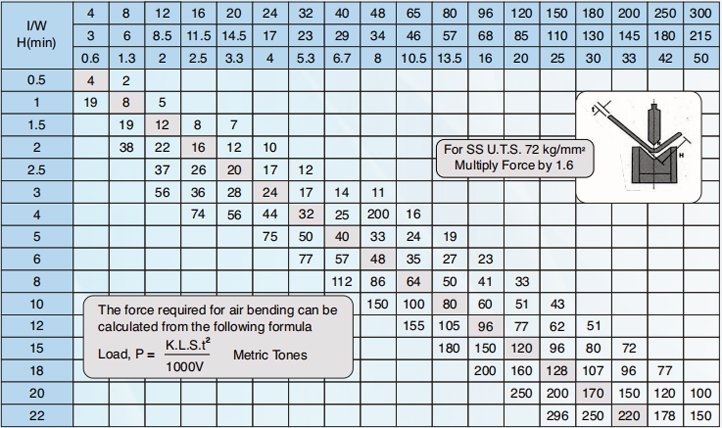
Bending Force Chart
The capacity of Press Brake is generally defined in tons. Followings contained the details of load calculation in different types of bending methods like Air Bending, Formind etc. These are certain special applications like piercing, straightening etc, which also be used on press brakes. But these processes need special tools & differet load calculations.
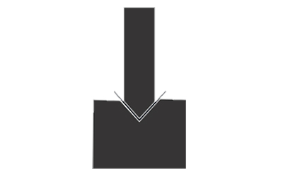
Air Bending is the most widely used applications on press brake, Air Bending is done on three contact lines, two die edge & cone punch edge, The calculations for air bending as per following.
| T Sheet Thickness in MM | 0.5mm - 8 mm | 9 mm - 10 mm | 12 mm or more |
| V - Die Opening | 8T | 10T | 12T |
In Bottom Bending the upper & lower dies are usually made with an include angle of 90° to ensure sharp corners on the formed part in the forming process, the dies strike solidly & squeeze the material at stroke bottom. This process requires 3 - 5 time the tonnage needed in air bending. Since more tonnage is required bottoming is seldom performed on steel greater than 12 gauge. The adjustable “V” die opening for bottoming are : V=5 to 6x material thickness.
The basic factors to be considered while selecting a press brake, or calculating the correct setting for operation are :
| Parameters | Unit |
| Plate Thickness (t) | mm |
| Ultimate Tensile Strength Of Plate (s) | Kg/mm² |
| Aluminium | 25 Kg/mm² |
| Mild Steel | 45 Kg/mm² |
| Stainless Steel | 72 Kg/mm² |
| Bending Length (L) | mm |
| Die Opening (V) | mm |
| Minimum Internal Radius | mm |
| Minimum Flange (H) | mm |
| Bending Correction Force (K) | 1.3 |
| Required Tonnage (P) | M. Tones |
Load, P (Metric Tones) = K x L x S x t / 1000 x V
P=1.3 (K) x 3000mm (L) x 45 (S) x 3.15² / 1000 (24 mm) = 72 Metric Tones
P=1.3(K) x 3000mm (L) x 45 (S) x 3.15² / 1000 (24 mm) = 115 Metric Tones
The bending chart also gives the bend radius & minimum bend edge also. The bending chart defines the load required per mm thickness per meter. To use bending chart, select the “V” opening from upper most line & thickness from vertical line, the matrix shows the total load in tons per meter. To achieve total load, this valve should be multiplied by the total length of job.
